UV dose (mJ/cm²) = UV intensity (mW/cm²) × exposure time (seconds). For drinking water disinfection, the WHO minimum is 40 mJ/cm² at the chamber's rated flow rate. To calculate the required dose for your application, you need: target pathogen, required log reduction, water UV Transmittance (UVT%), flow rate (LPH), and lamp output (mW/cm² at the sensor position).
Understanding how to calculate UV dosage for water disinfection is the foundation of every correctly sized UV system — whether you are specifying a 1,000 LPH residential unit or a 50,000 LPH municipal plant. UV dose is not a dial you set; it is the outcome of lamp intensity, chamber geometry, water quality, and hydraulic residence time interacting together. This guide walks through every parameter in the calculation, with tables, worked examples, and India-specific regulatory context.
The UV Dose Equation
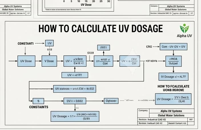
The fundamental relationship that governs how to calculate UV dosage for water disinfection is:
UV dose (mJ/cm²) = UV intensity (mW/cm²) × exposure time (seconds)
Breaking this down:
- UV intensity (E): the UV-C irradiance measured at the UV sensor position inside the chamber. It depends on lamp output power, chamber geometry, quartz sleeve transmittance, and the water's UV Transmittance (UVT%). It is not simply the lamp's rated wattage.
- Exposure time (t): how long a unit volume of water remains inside the irradiation zone. Calculated as: t (seconds) = chamber volume (L) ÷ flow rate (L/s).
The practical consequence is critical: at higher flow rates, exposure time drops and — if intensity is constant — delivered dose drops proportionally. A system rated at 40 mJ/cm² at 1,000 LPH will deliver approximately 20 mJ/cm² if you run it at 2,000 LPH. This is the most common sizing error in field installations.
Example: UV intensity at sensor = 10 mW/cm², exposure time = 4 seconds → UV dose = 10 × 4 = 40 mJ/cm² (WHO minimum for drinking water).
| Parameter | Symbol | Units | Typical value (residential system) |
|---|---|---|---|
| UV intensity at sensor | E | mW/cm² | 10–30 mW/cm² |
| Exposure time | t | seconds | 1–10 seconds |
| UV dose | D | mJ/cm² | 40 mJ/cm² (WHO minimum for drinking water) |
| Flow rate | Q | LPH or L/s | 1,000 LPH = 0.278 L/s |
| Chamber volume | V | Litres | 0.3–3 L depending on system |
Required UV Dose by Application and Pathogen
Before you can calculate UV dosage for water disinfection, you must know the target dose — which is determined by the pathogen and the required log reduction for your application. Not all pathogens require the same UV dose. Viruses typically require higher doses than bacteria; some protozoa (notably Cryptosporidium) are more sensitive to UV than they are to chlorine.
| Pathogen | 3-log reduction dose (mJ/cm²) | 4-log reduction dose (mJ/cm²) | Application standard |
|---|---|---|---|
| E. coli | 6 | 25 | Drinking water |
| Salmonella typhi | 10 | 40 | Drinking water |
| Vibrio cholerae | 3 | 12 | Drinking water |
| Giardia lamblia | 10 | 22 | Drinking water |
| Cryptosporidium parvum | 3 | 10 | Drinking water (extremely sensitive to UV — resistant to chlorine) |
| Rotavirus | 20 | 80 | Drinking water (viruses require higher dose) |
| Adenovirus | 60 | 186 | High-security water treatment |
| MS2 phage (surrogate virus) | 50 | 200 | Biodosimetry validation standard |
| USEPA UVDGM standard (drinking water) | — | 40 mJ/cm² | Municipal drinking water |
| WHO minimum (drinking water) | — | 40 mJ/cm² | All applications |
The 40 mJ/cm² standard is not an arbitrary number — at this dose, a properly designed system achieves 4-log E. coli, adequate Giardia and Cryptosporidium inactivation, and partial virus reduction. For adenovirus or MS2 phage targets (pharmaceutical or high-security municipal applications), doses of 80–200 mJ/cm² are required — which means either larger lamp power, lower flow rate, or multi-lamp chamber design.
UV Transmittance (UVT) — The Critical Water Quality Input
When engineers ask how to calculate UV dosage for water disinfection, UVT is the most commonly neglected variable. UV Transmittance measures what percentage of UV-C at 254 nm passes through a 1 cm column of the water to be treated. It directly controls how much of the lamp's output reaches pathogens at the far side of the chamber.
A system specified at UVT 75% and operated on water with UVT 55% will under-dose — potentially severely — without any visible indication during normal operation. The flow continues, the UV lamp illuminates, the alarm stays silent. This is why UVT measurement is not optional for any professionally designed UV system.
Simplified UVT correction for dose estimation:
Actual dose ≈ rated dose × (actual UVT / reference UVT)n where n is typically 0.5–1.0 (reactor geometry dependent).
Using n = 1 (conservative linear approximation): if your water has UVT 60% and the system is rated for UVT 75%, estimated delivered dose = 40 × (60/75) = 32 mJ/cm² — below the WHO minimum.
| Water UVT | Dose relative to UVT-75% rated dose | Disinfection status |
|---|---|---|
| 95% | 127% — significant safety margin | Very safe |
| 85% | 113% — extra margin | Safe |
| 75% | 100% — rated dose | Safe at rated flow |
| 65% | 87% | Marginal — reduce flow rate or pre-treat water |
| 55% | 73% | Insufficient at rated flow — pre-treatment required |
| 45% | 60% | Unsafe — pre-treatment mandatory before UV |
Standard UV system specifications are rated at UVT 75% (residential/commercial) or UVT 55% (STP/ETP tertiary treatment). If your water source UVT falls below the system's rating, the options are: reduce flow rate to extend exposure time, add pre-treatment (multimedia filter, iron removal, carbon filter) to raise UVT, or select a higher-power system rated for lower UVT.
How to Calculate Flow Rate Requirement
The flow rate is the variable you control — it determines exposure time and therefore dose. To correctly size a UV system, you must calculate peak flow demand, not average flow.
Step 1 — Measure peak demand: Time how long it takes to fill a 10-litre bucket at the peak draw point (the fastest tap or the pump outlet).
Step 2 — Calculate flow rate: Flow (LPH) = 10 ÷ fill time (seconds) × 3,600
Example: 10 L fills in 36 seconds → 10 ÷ 36 × 3,600 = 1,000 LPH
Step 3 — Apply safety margin: Design for 1.2× to 1.25× the measured peak flow to account for pressure fluctuations and future demand growth.
Step 4 — For multiple simultaneous users: Sum the coincident peak flows. In apartment complexes, apply a coincident use factor (typically 20–40% of total connected users drawing simultaneously during peak hour).
| Scenario | Fill time (10 L) | Calculated flow | Design flow (1.25× safety) | Recommended UV size |
|---|---|---|---|---|
| Single kitchen tap | 36 seconds | 1,000 LPH | 1,250 LPH | 1,500 LPH system |
| Restaurant kitchen (2 taps) | 18 seconds per tap | 2,000 LPH combined | 2,500 LPH | 3,000 LPH system |
| Borewell pump direct feed | Rated 2,000 LPH | 2,000 LPH | 2,500 LPH | 3,000 LPH system |
| Apartment complex (partial draw) | Multiple taps, 30% coincident | 10,000 LPH | 12,500 LPH | Multi-chamber system |
Lamp Power and Intensity Calculation
Low-pressure mercury UV lamps — including Philips TUV series lamps — emit approximately 30–35% of their electrical input power as UV-C at 254 nm. The rest is dissipated as heat and visible/infrared radiation. However, the UV-C output at the lamp surface is not the same as the UV intensity at the sensor position inside the chamber.
The path from lamp output to delivered UV dose involves: quartz sleeve transmittance (typically 90–95% for high-quality quartz), water absorption (a function of UVT), chamber geometry (diameter, length, reflectivity of chamber walls), and hydraulic flow distribution (non-uniform flow creates regions of shorter residence time). This is why you cannot calculate lamp-to-dose yourself for regulatory compliance purposes — you must use manufacturer-validated performance data.
For residential and commercial selection: use the manufacturer's published rated flow at 40 mJ/cm², validated at the stated UVT. This is the number that matters for compliance.
For engineering design (municipal, pharmaceutical, industrial): use CFD (Computational Fluid Dynamics) modelling and biodosimetry validation per USEPA UVDGM or DVGW W294 protocol.
| Lamp (Philips TUV) | Input power | UV-C output (254 nm) | Typical system flow range |
|---|---|---|---|
| TUV 5W | 5W | 1.5W UV-C | 250–500 LPH |
| TUV 11W | 11W | 3.5W UV-C | 750–1,500 LPH |
| TUV 25W | 25W | 8W UV-C | 2,000–3,000 LPH |
| TUV 55W | 55W | 18W UV-C | 4,000–6,000 LPH |
| TUV 150W | 150W | 50W UV-C | 15,000–25,000 LPH |
These flow ranges assume standard chamber geometries at UVT 75–85% and 40 mJ/cm² target dose. Actual validated performance will vary by chamber design. Always verify against the specific system's biodosimetry data sheet.
Log Reduction Requirement Calculation
Log reduction quantifies disinfection efficacy. The formula is:
Log reduction = log₁₀ (influent pathogen count ÷ effluent pathogen count)
In practice: 2-log = 99% reduction; 3-log = 99.9% reduction; 4-log = 99.99% reduction. The difference between 3-log and 4-log is one additional order of magnitude kill — not a 25% improvement. This is why regulatory standards are specific about which log reduction they require.
How to determine required log reduction for your application:
- WHO drinking water: 4-log reduction for reference pathogens (E. coli, rotavirus, Cryptosporidium). This maps to 40 mJ/cm² for the bacterial and protozoan targets; higher doses required if adenovirus is a regulatory concern.
- STP/ETP reuse water (CPCB Class A): 3-log reduction for total coliform — typically 25 mJ/cm² is sufficient, though 40 mJ/cm² is recommended for additional safety margin.
- Pharmaceutical purified water (Schedule M 2025): bioburden reduction requirement is system and product-specific. 40 mJ/cm² minimum is standard practice; validation against the specific bioburden action limit for the purified water loop is required.
| Application | Target pathogen | Required log reduction | Required UV dose | Indian standard |
|---|---|---|---|---|
| Municipal drinking water | E. coli | 4-log | 40 mJ/cm² | BIS IS 10500 |
| STP Class A reuse | Total coliform | 3-log | 25 mJ/cm² | CPCB Class A |
| Food process water | E. coli | 4-log | 40 mJ/cm² | FSSAI Schedule 4 |
| Pharma purified water | Bioburden reduction | Application-specific | 40 mJ/cm² minimum | Schedule M 2025 |
| Aquaculture (Vibrio) | Vibrio spp. | 3-log | 30 mJ/cm² | State fisheries norms |
Biodosimetry: How UV Systems Are Validated
Biodosimetry is the gold-standard method for validating that a UV system actually delivers its rated dose under real operating conditions. It cannot be replaced by calculation — not even with CFD modelling, which predicts dose distribution but must itself be validated against measured biological response.
How biodosimetry works: the UV system is challenged with a known concentration of a biological surrogate — MS2 bacteriophage (a harmless virus surrogate) or Bacillus subtilis spores — at a defined flow rate and UVT. The log reduction of the surrogate is measured at the system outlet. Since the dose-response relationship of the surrogate is independently characterised, the measured log reduction is converted to the equivalent UV dose delivered by the system.
This accounts for all real-world factors that simplified intensity-time calculations miss: hydraulic short-circuiting (where some water moves through faster than average), lamp ageing effects on UV-C output, quartz sleeve fouling, and flow non-uniformity across the chamber cross-section.
Key validation standards used in India:
- USEPA UVDGM (EPA 815-R-06-007): challenge test with MS2 phage; required for US municipal validation; referenced in India for pharmaceutical export compliance.
- DVGW W294 (Germany): European validation standard accepted by Indian pharma and food export companies for CE-compliant UV systems.
- ÖNORM M 5873 (Austria): often used by European UV system suppliers operating in India; employs Bacillus subtilis spore surrogate at 254 nm.
The practical implication for procurement: when a manufacturer states "40 mJ/cm² at 1,000 LPH, UVT 75%", this must be biodosimetry-validated data — not a calculation from lamp wattage. Always request the biodosimetry validation certificate, specifying which standard was used, which accredited test laboratory performed it, and at what UVT the test was conducted.
Quick Reference: UV Dose Design Table for India 2026
This table consolidates the calculation steps above into a practical reference for common Indian applications. All doses are at 40 mJ/cm² (WHO/BIS standard) unless noted. Philips TUV lamp selection is indicative — actual system selection must be based on validated dose data for the specific chamber model.
| Application | Flow (LPH) | UVT assumed | Required dose | Lamp (Philips TUV) | Notes |
|---|---|---|---|---|---|
| Home kitchen (4–6 persons) | 1,000 | 85% municipal | 40 mJ/cm² | 11W TUV | Pre-filter essential; replace lamp annually |
| Home borewell (4–6 persons) | 1,000 | 75% after pre-filter | 40 mJ/cm² | 11W TUV | Iron pre-filter required if Fe > 0.3 mg/L |
| Restaurant kitchen (50 covers) | 2,000 | 80% municipal | 40 mJ/cm² | 25W TUV | Carbon pre-filter for taste; FSSAI Schedule 4 |
| STP tertiary (100 KLD plant) | 4,200 | 55% post-bio | 25 mJ/cm² | 55W TUV | Open channel option; CPCB Class A reuse |
| Pharma PW loop | 2,000 | 90% after RO | 40 mJ/cm² | 25W TUV | SS 316L wetted parts; UV intensity monitor mandatory; Schedule M 2025 |
Frequently Asked Questions
Can I calculate the UV dose I need myself without a manufacturer?
You can calculate an indicative dose using the formula UV dose = intensity × time, and estimate required dose from pathogen tables. However, for any regulated application (drinking water supply, food processing, pharmaceutical, STP reuse), the system delivering that dose must have biodosimetry-validated performance data — not a hand calculation. The calculation tells you what you need; biodosimetry validation proves the system delivers it. These are two different things, and both are necessary.
What is the minimum UV dose for safe drinking water?
The WHO Guidelines for Drinking Water Quality and BIS IS 10500:2012 both specify 40 mJ/cm² as the minimum UV dose for drinking water disinfection. This dose achieves 4-log E. coli reduction, adequate Giardia and Cryptosporidium inactivation, and partial inactivation of most viruses. Systems must deliver this dose at the rated flow rate and at the specified UVT — exceeding the rated flow, or operating on water with lower UVT than specified, will reduce the delivered dose below 40 mJ/cm².
How does flow rate affect UV dose?
Flow rate and UV dose are inversely proportional at constant lamp intensity. If you double the flow rate through the same chamber, you halve the hydraulic residence time, which halves the UV dose. A system rated at 40 mJ/cm² at 1,000 LPH will deliver approximately 20 mJ/cm² at 2,000 LPH. This is why peak flow rate — not average flow — must be used when sizing a UV system. Never install a system rated for less than your measured peak flow rate.
What UV dose is required for Cryptosporidium?
Cryptosporidium parvum is highly sensitive to UV-C at 254 nm. A UV dose of just 3 mJ/cm² achieves 3-log reduction, and 10 mJ/cm² achieves 4-log reduction. This contrasts sharply with chlorine, which cannot inactivate Cryptosporidium at practical dosing levels in cold water. For surface water treatment where Cryptosporidium is a risk (post-monsoon, river-fed sources), the standard 40 mJ/cm² UV dose provides more than adequate Cryptosporidium protection — it is governed by other pathogens (E. coli 4-log, virus targets) rather than Cryptosporidium specifically.
Can I increase UV dose by running a larger lamp in my chamber?
Not safely. UV chambers are engineered around specific lamp geometries — lamp diameter, arc length, quartz sleeve clearance, and chamber diameter are all matched to the design lamp. Installing a physically larger lamp may not fit the quartz sleeve, will alter the hydraulic flow profile in ways not accounted for in the original chamber design, and will generate heat that the lamp holder and ballast may not be rated to handle. To increase UV dose, select a chamber specifically designed and validated for the higher output — do not modify the lamp in an existing chamber.
How do I verify my UV system is delivering the correct dose?
There are three practical methods. First, continuous UV intensity monitoring: most commercial and industrial UV systems include a UV sensor inside the chamber; the sensor reading (in mW/cm²), combined with the known flow rate, gives a real-time dose estimate. Second, periodic biodosimetry: for regulated applications (pharma, municipal), periodic challenge testing with a biological surrogate at the installed flow rate confirms actual delivered dose, not just lamp intensity. Third, microbiological water testing: regular outlet water testing for E. coli and total coliform per IS 1622 confirms that the system is achieving its required log reduction in service. All three methods together form a complete UV dose verification programme.
Our engineering team calculates UV dose requirements for every project — residential, commercial, pharmaceutical, and municipal. Share your flow rate, water source, and application and we will specify the correct system with full UV dose data. Response within 24–48 hours.
WhatsApp Us for a UV Dose CalculationStandards, authorities & further reading
External references used to inform this guide. Regulations evolve — check the latest revision on each authority's site before compliance decisions.
Recommended UV Systems
Alpha UV System products for this application — powered by genuine Philips UV-C lamps.
Industrial UV Water Treatment System
5,000 – 50,000 LPH
Schedule M 2025 and HACCP compliant UV for pharma, food & beverage, and process water
Commercial UV Water Purification System
500 – 5,000 LPH
HACCP-compliant UV water purification for hotels, restaurants, and offices
Not sure which system suits your application? WhatsApp our engineers for a free recommendation →
Related solutions
See how Alpha UV System applies this to your industry or city.
Need a UV system?
Talk to our UV engineers — WhatsApp for a quote in 2 hours, or browse the full catalog on IndiaMART.