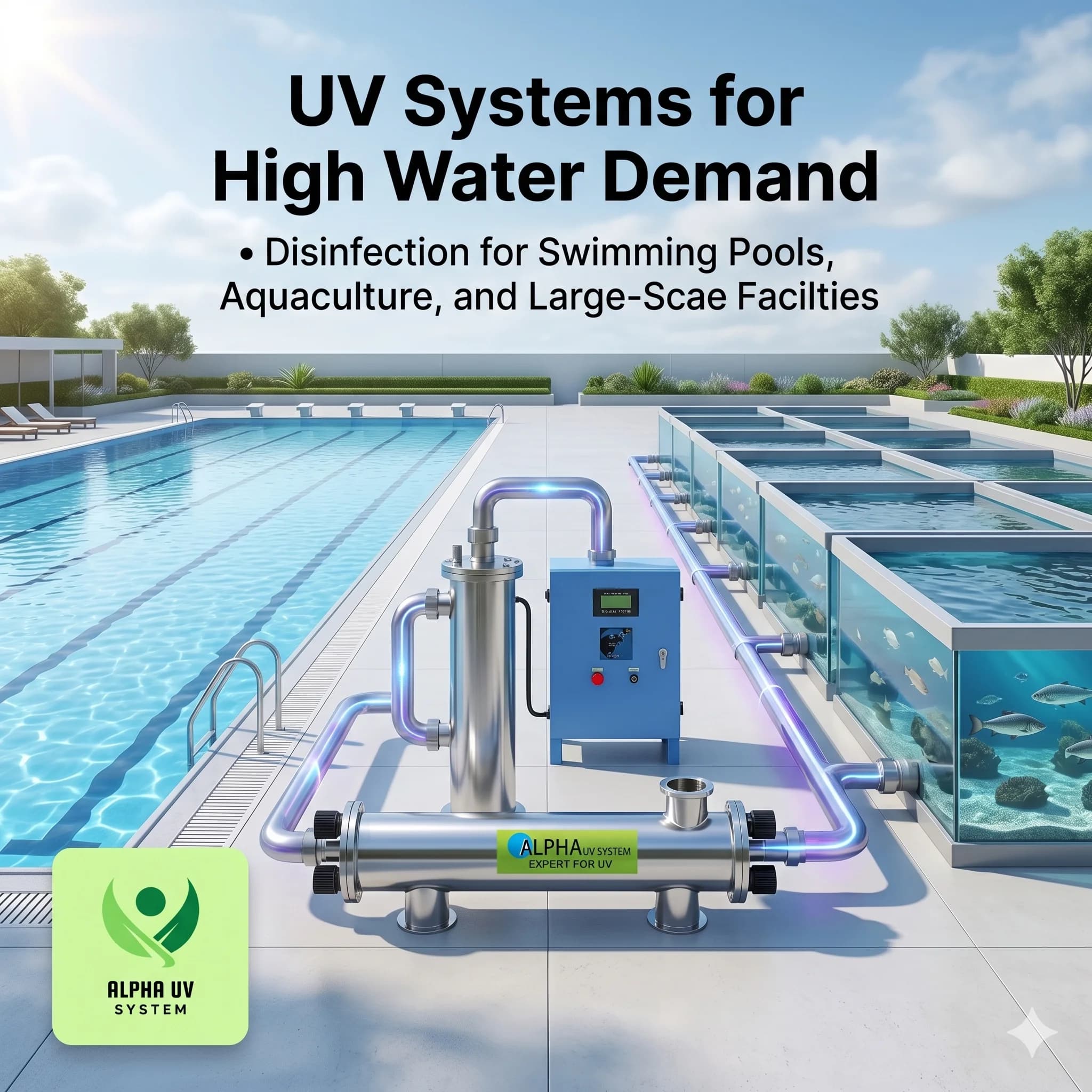
UV systems scale from 100 LPH household units to millions of litres per hour for municipal plants. Scaling is achieved through multi-lamp chambers, parallel UV trains, and open-channel reactors — never by exceeding a single unit's rated capacity. For high water demand in India (apartments, hotels, factories, municipalities), Alpha UV supplies validated UV systems from 2,000 LPH to 5,00,000 LPH with Philips UV-C lamps and guaranteed 40 mJ/cm² dose.
UV systems for high water demand and large flow rate applications are a critical infrastructure requirement across India — from 500-flat apartment complexes in Bengaluru and Pune to 300-room hotels in Delhi NCR, from food processing plants in Gujarat and Maharashtra to municipalities rolling out treatment under Jal Jeevan Mission. The engineering challenge is not whether UV technology can scale — it can, without any upper theoretical limit — but how to scale it correctly so that every litre of water receives the design UV dose regardless of flow rate fluctuation. This guide covers the complete engineering framework for sizing, designing, and operating UV systems for high water demand and large flow rate sites in India.
Why Exceeding Rated Flow Is Dangerous
UV dose is the product of lamp UV output and the time the water spends in the UV field (exposure time). At higher flow rates, water moves through the UV chamber faster, reducing exposure time — and therefore reducing the delivered UV dose. This relationship is direct and predictable: a UV system running at 150% of its rated flow will deliver significantly less than the design dose. The danger is that the lamp indicator light still shows green throughout. The system appears to be working. The failure is completely invisible to the operator.
The minimum dose for full 4-log pathogen inactivation (99.99% kill of bacteria, viruses, and protozoa including Giardia and Cryptosporidium) in drinking water is 40 mJ/cm². Below this threshold, pathogen inactivation is partial. At 27 mJ/cm² — the approximate dose at 150% rated flow — certain viruses and protozoa survive. At 20 mJ/cm² — the approximate dose at 200% rated flow — multiple classes of pathogens survive in numbers that constitute a serious public health risk. UV systems for high water demand must therefore be sized to deliver 40 mJ/cm² at the peak flow rate, not the average flow rate.
| Flow as % of Rated | UV Dose Delivered | Disinfection Status | Risk |
|---|---|---|---|
| Up to 100% | 40 mJ/cm² | Safe — 4-log kill | None |
| 110% | 36 mJ/cm² | Adequate | Minimal |
| 125% | 32 mJ/cm² | Borderline | Some viruses may survive |
| 150% | 27 mJ/cm² | Insufficient | Significant pathogen risk |
| 200% | 20 mJ/cm² | Dangerous | Major pathogen risk |
| 300% | 13 mJ/cm² | Unsafe | No meaningful disinfection |
How UV Systems Scale for High Water Demand
Three proven engineering approaches allow UV systems for high water demand and large flow rate applications to maintain guaranteed dose at any scale. The correct approach depends on the flow range and application type.
Approach 1 — Multi-Lamp Single Chamber
Multiple Philips UV-C lamps are installed inside a single larger-diameter stainless steel chamber. A 2-lamp chamber delivers roughly twice the UV dose per unit volume compared to a single-lamp chamber of the same length, enabling higher rated flow at the same chamber dimensions. Commercial and industrial multi-lamp chambers are available with 2, 4, 6, and 8 lamps. Each lamp operates on its own electronic ballast — a single ballast failure affects only one lamp, and the system continues operating at reduced capacity with an alarm. Multi-lamp single-chamber systems handle UV systems for high water demand up to approximately 50,000 LPH in a single unit.
Approach 2 — Parallel UV Trains
For flow rates above 50,000 LPH, multiple identical UV chambers are installed in parallel on a common inlet and outlet manifold. Each train handles a defined fraction of the total flow — for example, three parallel trains each rated at 60,000 LPH together handle 1,80,000 LPH total. The manifold distributes flow evenly across trains. If one train is shut down for lamp replacement or maintenance, the others continue treating water at full rated capacity. Parallel UV trains are the standard configuration for large industrial sites and township water supply in India, and are capable of handling UV systems for high water demand and large flow rate requirements up to 5,00,000 LPH and beyond.
Approach 3 — Open-Channel UV Reactor
At municipal scale, UV lamp arrays are suspended horizontally above or within an open concrete or stainless steel channel through which water flows by gravity. Water passes beneath the lamp arrays and receives its UV dose as it flows past. Open-channel UV reactors eliminate the pressure constraints of closed-vessel chambers, making them the most practical configuration for flows above 5,00,000 LPH. They are the preferred technology for new municipal STPs and WTPs under the Jal Jeevan Mission, AMRUT, and Smart Cities programme. Access for lamp replacement is straightforward — lamp modules lift vertically out of the channel without interrupting flow.
| Flow Range | Scaling Approach | UV System Type | Typical Application |
|---|---|---|---|
| 100–2,000 LPH | Single lamp | Standard residential/commercial | Homes, small offices |
| 2,000–10,000 LPH | 2–4 lamp chamber | Commercial multi-lamp | Hotels, restaurants, schools |
| 10,000–50,000 LPH | Multi-lamp or 2–3 parallel | Industrial inline | Factories, apartment complexes |
| 50,000–5,00,000 LPH | Parallel trains | Multiple chambers in manifold | Large industrial, township water |
| Above 5,00,000 LPH | Open-channel reactor | UV arrays over channel | Municipal water treatment plant |
High-Demand Applications in India
India's diverse building stock and rapidly expanding water infrastructure create a wide range of UV systems for high water demand and large flow rate requirements. The following table maps common Indian building and industrial types to their UV system sizing requirements.
| Application | Typical Daily Flow | Peak Hourly Flow | Required UV Size | Indian Examples |
|---|---|---|---|---|
| 5-star hotel (300 rooms) | 3,00,000 L/day | 30,000 LPH | 30,000–50,000 LPH system | Delhi NCR, Mumbai, Goa hotels |
| Apartment complex (500 units) | 5,00,000 L/day | 50,000–80,000 LPH | 80,000 LPH system | Bengaluru, Pune, Hyderabad |
| Hospital (300 beds) | 2,00,000 L/day | 20,000 LPH | 25,000 LPH system | Major cities |
| Food processing plant | Variable | 10,000–1,00,000 LPH | Multi-lamp or parallel trains | Gujarat, Maharashtra, Tamil Nadu |
| Bottled water plant | Variable | 5,000–50,000 LPH | 10,000–60,000 LPH system | All India |
| Municipal WTP (small town) | 50,00,000 L/day | 5,00,000 LPH | Open-channel UV | Tier-2/3 cities under Jal Jeevan Mission |
Calculating Flow Rate Demand for High-Demand Sites
The most common sizing error for UV systems for high water demand and large flow rate applications is using average daily demand rather than peak hourly demand as the design basis. A UV system sized on average daily flow will be undersized for the actual peak demand — the precise condition where inadequate dose causes a pathogen risk. The correct approach is always to size on peak hourly demand, then add a safety margin.
Peak Demand Calculation
Peak hourly demand = (Daily volume × Peak hour factor) ÷ Number of operating hours in the peak period. For apartment complexes, coincident demand is also relevant — only 30–40% of flats draw water simultaneously even during morning peak, so the peak flow is lower than if every unit drew water at once. For hotels, the breakfast period typically generates 2× the hourly average flow; kitchen demand should be calculated separately from room supply demand. Always add a 20–25% safety margin above the calculated peak demand to account for demand growth, measurement uncertainty, and future expansion.
| Building Type | Daily Demand Basis | Peak Hour Factor | Safety Margin |
|---|---|---|---|
| Apartment residential | 135 L/person/day | 2.0–2.5× hourly average | 20% |
| Hotel (all amenities) | 250–500 L/room/day | 2.0–3.0× hourly average | 25% |
| Hospital | 340 L/bed/day | 1.5–2.0× hourly average | 25% |
| School / college | 45 L/student/day | 3.0–4.0× (during breaks only) | 20% |
| Industrial / factory | Process-dependent | 1.0–1.5× (usually even) | 25% |
Parallel UV Train Design
Parallel UV trains are the backbone engineering solution for UV systems for high water demand and large flow rate applications between 50,000 LPH and 5,00,000 LPH. Each parallel train is a fully independent UV system — its own chamber, its own Philips UV-C lamps, its own electronic ballasts, and its own UV intensity monitor. The trains share only the inlet and outlet manifolds.
The manifold is engineered to distribute flow evenly across all trains. Uneven flow distribution is a design failure — a train receiving 40% more flow than others will deliver sub-design dose. Flow balancing is achieved through equal-length branch pipework, balancing valves commissioned on-site, or a common header design that equalises pressure at each branch takeoff.
N+1 Redundancy: The recommended design for UV systems for high water demand applications is N+1 redundancy — one more train than the minimum needed to treat the total flow. A common configuration is three parallel trains each operating at 40% of capacity, giving a combined capacity of 120% of design flow and a 20% reserve. If one train shuts down for lamp replacement, the remaining two trains still handle 80% of design flow, which covers most non-peak demand periods. For critical applications (hospital, pharmaceutical, municipal water supply), true N+1 means the system can handle 100% of peak flow with one train fully offline.
Maintenance advantage: One of the primary operational benefits of parallel UV trains is that lamp replacement in one train can proceed while the others continue treating water. There is no need to interrupt water supply to the facility during routine lamp replacement. This is a significant advantage at high-demand sites like 5-star hotels in Delhi NCR or large apartment complexes in Hyderabad and Pune where uninterrupted water supply is a non-negotiable requirement.
Open-Channel UV Reactors for Municipal Scale
Open-channel UV reactors bring UV disinfection to flows that would require impractically large and expensive pressurised chambers. The configuration is straightforward: banks of Philips TUV lamps are suspended horizontally, either above or partially submerged in, an open concrete or stainless steel channel. Water flows through the channel by gravity, and as it passes the lamp arrays, it receives its UV dose. Multiple lamp banks can be arranged in series to increase delivered dose for lower-UVT water, or in parallel channels to increase total flow capacity.
Open-channel UV is well-suited to Indian municipal applications for several reasons. First, municipal STPs and WTPs in India typically use gravity-flow channels throughout the treatment train — open-channel UV integrates naturally into existing channel infrastructure without adding pump heads or pressure pipes. Second, lamp access is vertical and from above — no confined space entry, no dewatering, and no system shutdown required for routine lamp replacement. Third, the CPHEEO (Central Public Health and Environmental Engineering Organisation) guidelines accept open-channel UV for flows above 50,000 LPH in municipal applications.
Municipalities in Tier-2 and Tier-3 cities receiving funding under Jal Jeevan Mission and AMRUT are increasingly specifying UV disinfection as the final treatment step for piped water supply schemes. Open-channel UV satisfies this requirement at municipal scale while meeting IS 10500:2012 standards for drinking water microbial quality. Smart Cities programme projects in Gujarat, Maharashtra, Tamil Nadu, and Telangana are also incorporating open-channel UV in their water treatment plant upgrades.
Power Supply and Redundancy for High-Demand UV Systems
Each Philips UV-C lamp in a large UV system requires its own electronic ballast. In multi-lamp systems, individual ballast-per-lamp design means a single ballast failure takes down only one lamp — not the entire system. The UV intensity monitor detects the lamp failure and triggers an alarm, but the remaining lamps continue treating water at reduced — though potentially still adequate — dose while the failed lamp is being replaced.
Power consumption scales directly with system size. The power requirement for UV systems for high water demand and large flow rate installations must be factored into facility electrical planning. At 2,00,000 LPH with eight 300W Philips UV-C lamps, total UV system power draw is 2,400W — modest for a facility of this scale, but it should be on a dedicated circuit with an isolator.
| System Size | Wattage per Lamp | Lamps | Total Power | Monthly Electricity Cost (₹6/kWh) |
|---|---|---|---|---|
| 1,000 LPH | 11W | 1 | 11W | ₹48 |
| 10,000 LPH | 65W | 2 | 130W | ₹562 |
| 50,000 LPH | 150W | 4 | 600W | ₹2,592 |
| 2,00,000 LPH | 300W | 8 | 2,400W | ₹10,368 |
UPS for critical applications: Hospitals, pharmaceutical manufacturing sites, and municipal water supply installations should install a UPS on the UV system power supply to bridge grid power cuts without interrupting disinfection. During a grid power cut without UPS, the lamps extinguish and flow must be halted. Alpha UV industrial systems include a solenoid valve interlock as standard — when UV power is interrupted, the solenoid valve on the outlet closes, preventing any untreated water from passing through the system to distribution. When power is restored and lamps reach full intensity (typically 30–60 seconds for warm restart), the solenoid reopens automatically.
UV System Monitoring at Scale
Large UV systems for high water demand and large flow rate applications require instrumentation beyond the basic lamp-on indicator light. The following monitoring and control features are standard or available on Alpha UV industrial systems.
UV Intensity Monitors: A calibrated UV sensor in the chamber wall measures the actual UV intensity reaching the sensor in real time. This confirms that the lamps are delivering adequate intensity — not just that they are electrically powered. Intensity monitors are mandatory for commercial and industrial UV systems under FSSAI Schedule M requirements and are strongly recommended for any system above 2,000 LPH.
SCADA Integration: Large parallel UV train installations connect to the facility's building management system (BMS) or plant SCADA via Modbus or digital I/O. SCADA integration allows remote monitoring of lamp status, UV intensity readings, flow rates, and alarm events from the central control room — important for UV systems for high water demand applications where the UV system room may be in a remote basement or plant room.
Data Logging: For FSSAI, Schedule M GMP, and CPCB compliance, Alpha UV industrial systems log lamp operating hours, UV intensity readings, and alarm events with timestamps. This log is the primary compliance record demonstrating that water was treated to the design dose throughout the operating period. The data logger stores a minimum of 12 months of records and can export to USB or network share.
Remote Monitoring and Alarms: Alpha UV industrial systems support GSM/GPRS-based alarm notification for remote or unattended sites — for example, a UV system serving a township water supply that is not continuously staffed. When a lamp fails or UV intensity drops below the setpoint, an SMS alert is sent to the designated maintenance number. Response time for field service from Alpha UV is 24–48 hours.
Predictive Lamp Replacement: Every Alpha UV industrial system includes a running hours counter. Philips UV-C lamps are rated for 9,000 hours of output at or above 70% of initial intensity (the standard end-of-life criterion). The control panel displays remaining lamp life and triggers a replacement warning at 8,000 hours — giving the operator approximately one month's advance notice to order and schedule lamp replacement without any emergency downtime.
Frequently Asked Questions
How many UV units do I need for a 500-flat apartment complex?
A 500-flat apartment complex typically has a daily water demand of 4,00,000–5,00,000 litres (assuming 135 L/person/day with average 5–6 persons per flat and 65–70% occupancy). Peak hourly demand during the morning supply period is typically 50,000–80,000 LPH. The correct configuration for UV systems for high water demand at this scale is either one 80,000 LPH multi-lamp system or two parallel 50,000 LPH systems with N+1 redundancy. Alpha UV recommends two parallel systems for large apartment complexes in Bengaluru, Pune, and Hyderabad because it enables one system to be serviced without interrupting water supply.
Can a single UV chamber handle 1,00,000 LPH?
A single large-diameter multi-lamp UV chamber can handle up to approximately 50,000–60,000 LPH with currently available chamber and lamp configurations using Philips UV-C lamps. At 1,00,000 LPH, the standard engineering solution is two parallel UV trains each rated at 60,000 LPH, giving 20% excess capacity and the ability to maintain full treatment with one train in maintenance. Single chambers at 1,00,000 LPH are not recommended because they create a single point of failure with no redundancy.
What happens to UV disinfection during a power cut?
When grid power is interrupted, Philips UV-C lamps extinguish immediately. Alpha UV industrial systems include a solenoid valve interlock that closes the outlet valve within seconds of power loss, preventing untreated water from reaching distribution. Water supply is temporarily interrupted. When power is restored, the lamps reach operating intensity within 30–60 seconds (warm restart) and the solenoid valve reopens automatically. For sites where water supply interruption is not acceptable during power cuts — hospitals, pharmaceutical sites, critical municipal supply — a UPS sized for the UV system power load should be installed. Alpha UV provides UPS integration as an optional add-on for all industrial UV systems.
How do I verify a large UV system is delivering adequate dose?
The UV intensity monitor is the primary real-time verification instrument. It measures actual UV intensity in the chamber and confirms the system is operating within specification. For formal validation — required for pharmaceutical manufacturing (Schedule M), food processing (FSSAI), and municipal water supply — biodosimetry testing is performed: a challenge microorganism (typically MS2 bacteriophage) is dosed into the influent and the log reduction at the system outlet is measured to confirm delivered dose meets the design minimum of 40 mJ/cm². Alpha UV provides biodosimetry testing coordination and commissioning documentation for all industrial UV systems above 10,000 LPH.
What is the commissioning process for a large industrial UV system?
Commissioning for UV systems for high water demand and large flow rate applications involves the following steps: (1) Installation verification — confirm all mechanical connections, electrical connections, and safety interlocks are correct; (2) Lamp pre-soak — run Philips UV-C lamps for 100 hours before performance testing to allow lamp output to stabilise; (3) Flow calibration — verify actual flow through each parallel train matches design using an inline flow meter; (4) UV intensity baseline — record initial UV intensity readings at design flow to establish the baseline against which future lamp degradation is tracked; (5) Solenoid valve interlock test — confirm the solenoid closes on simulated power failure; (6) Alarm function test — confirm all alarm outputs (lamp failure, low intensity, flow high) function correctly; (7) Documentation package — deliver the commissioning report, UV dose calculation, lamp COA, and O&M manual. Alpha UV provides a complete commissioning package within 48 hours of commissioning completion.
How often should lamps be replaced in a large multi-lamp UV system?
Philips UV-C lamps in Alpha UV industrial systems are rated for 9,000 hours of operation at or above 70% of initial output (the point at which delivered dose at rated flow drops to 40 mJ/cm² — the design minimum). At 24-hour continuous operation, this corresponds to approximately 12.5 months. At 16-hour operation per day, the replacement interval extends to approximately 18–19 months. Alpha UV recommends annual lamp replacement as a practical maintenance schedule for most industrial applications running 16–24 hours per day. For UV systems in pharmaceutical and food processing sites where regulatory compliance requires maintained dose with a margin, replacement at 8,000 hours (before the 9,000-hour end-of-life) is recommended. Philips TUV lamp replacement is available from Alpha UV with 24–48 hour dispatch for all Alpha UV system models.
Alpha UV supplies validated UV systems from 2,000 LPH to 5,00,000 LPH with Philips UV-C lamps and 40 mJ/cm² guaranteed dose. Response within 24–48 hours for sizing, quotation, and technical specification.
WhatsApp for UV System SizingStandards, authorities & further reading
External references used to inform this guide. Regulations evolve — check the latest revision on each authority's site before compliance decisions.
Recommended UV Systems
Alpha UV System products for this application — powered by genuine Philips UV-C lamps.
Commercial UV Water Purification System
500 – 5,000 LPH
HACCP-compliant UV water purification for hotels, restaurants, and offices
Industrial UV Water Treatment System
5,000 – 50,000 LPH
Schedule M 2025 and HACCP compliant UV for pharma, food & beverage, and process water
Not sure which system suits your application? WhatsApp our engineers for a free recommendation →
Related solutions
See how Alpha UV System applies this to your industry or city.
Need a UV system?
Talk to our UV engineers — WhatsApp for a quote in 2 hours, or browse the full catalog on IndiaMART.