Quick Answer
Correct UV system installation requires: a straight pipe run of ≥5× pipe diameter upstream of the UV reactor (to eliminate turbulent flow that creates dose-distribution dead zones), pre-filtration to ≤5 micron and turbidity ≤1 NTU before the UV reactor inlet, isolation valves and a bypass line on both sides of the reactor (for maintenance without shutting down the system), correct lamp orientation (horizontal preferred for most reactor designs), and wiring of the UV intensity alarm relay to the downstream flow control so that flow stops automatically if UV intensity drops below the dose-delivery threshold. A UV system that is physically installed but not commissioned — meaning UV intensity has not been verified against the design dose at the actual operating flow rate — is not a functioning disinfection system regardless of how new the equipment is. Commissioning requires measuring UV intensity with a calibrated meter at the rated flow rate and confirming it meets the validated dose. This guide covers every step from delivery inspection to ongoing annual service.
Before UV Installation: Site and Water Quality Checks
The most common cause of UV disinfection failure in India is not equipment malfunction — it is incorrect installation into a site that was not properly assessed before the UV reactor arrived. A site assessment before UV installation should confirm four things:
Pre-Treatment Requirements
UV disinfection systems require water to meet minimum clarity standards before the reactor inlet. Suspended particles — soil, iron floc, organic matter — absorb and scatter UV light, creating "shadow zones" where bacteria can shelter and survive the UV dose. The pre-treatment requirements before UV installation are:
- Turbidity: ≤1 NTU. Measured with a turbidity meter, not visual inspection. Water that looks clear to the eye can have 5–8 NTU turbidity during monsoon or after tank cleaning — enough to reduce UV dose delivery by 30–40%.
- Iron: ≤0.3 mg/L. Iron above this level precipitates on the quartz sleeve, forming a brown deposit that blocks UV transmission and requires sleeve cleaning every 4–8 weeks rather than every 6–12 months.
- Hardness / scale: Water with total hardness above 300 mg/L (as CaCO₃) will cause calcium carbonate scale on the quartz sleeve at operating temperatures. An antiscalant dosing system or water softener upstream is required for hard groundwater sources common in Rajasthan, Gujarat, Maharashtra, and parts of UP.
- UV transmittance (UVT): Measure with a UV spectrophotometer at 254 nm before specifying the UV system. If UVT is below 75%, the UV reactor may need to be oversized or a different pre-treatment step (activated carbon filtration for organic-laden water, or ultrafiltration for STP effluent) added before the reactor.
If pre-filtration is not in place, install a 5-micron cartridge filter or multimedia filter before the UV reactor. This is not optional — it is a functional requirement for dose guarantee.
Hydraulic Requirements
UV reactors require fully developed, uniform pipe flow at the inlet for even UV dose distribution across the flow cross-section. Turbulent flow patterns from nearby elbows, valves, or tees create channelling — fast-moving streams of water that pass through the reactor with insufficient exposure time. The minimum hydraulic requirements for UV installation are:
- Straight pipe run: ≥10× pipe diameter upstream (5× minimum, 10× preferred for horizontal reactors)
- Straight pipe run: ≥5× pipe diameter downstream before the first elbow or valve
- No pump discharge connections within 5× diameter upstream — pump discharge creates axial rotation in the flow that causes dose non-uniformity
- No partially-open gate valves or throttled butterfly valves within 3× diameter — these create wake turbulence and localized high-velocity zones
In existing plant installations where straight runs are constrained, flow conditioning plates or static mixers can be installed upstream to homogenise the velocity profile. Alpha UV System's engineering team assesses hydraulic conditions during pre-installation site surveys and recommends flow conditioning where required.
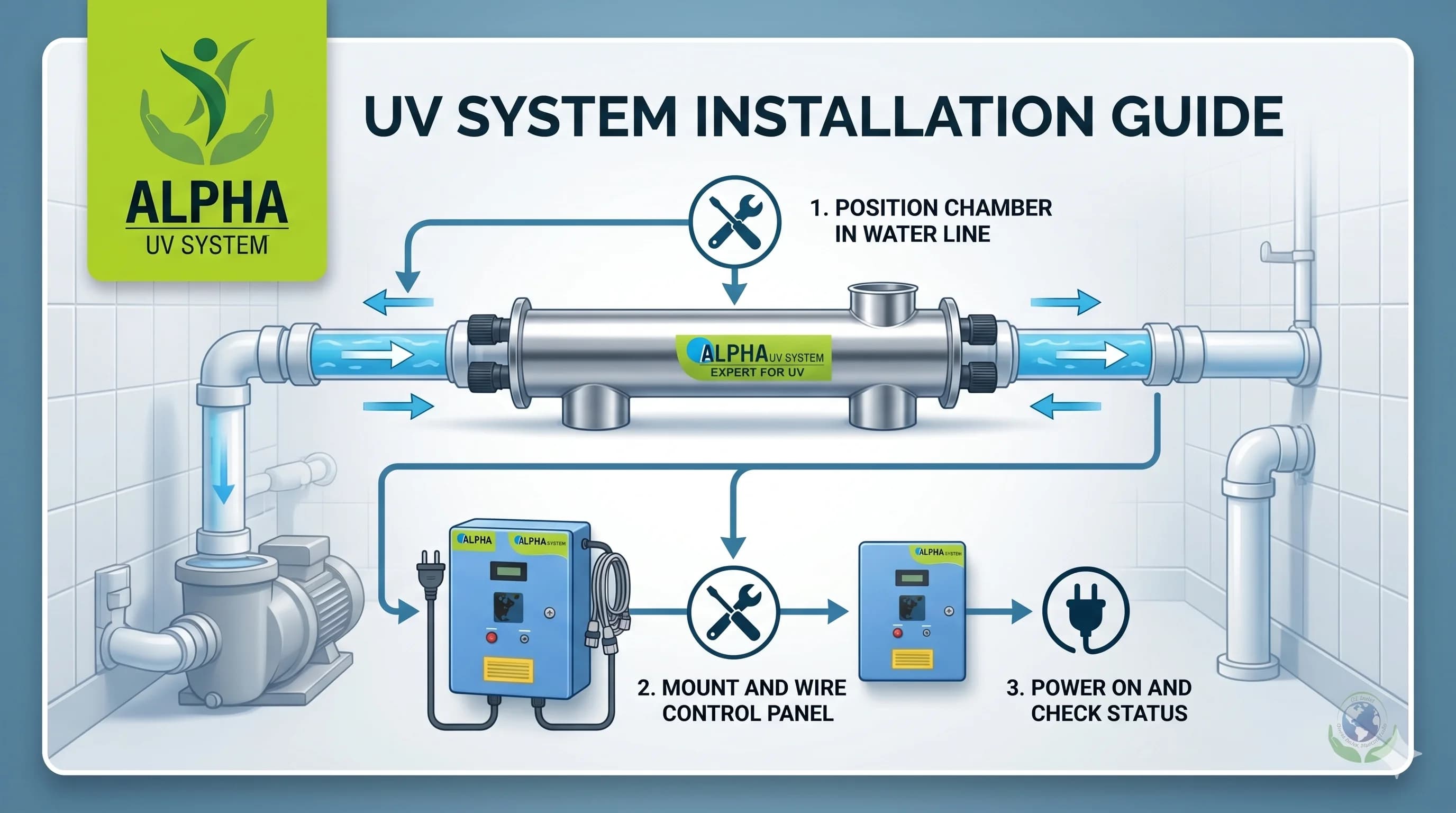
UV System Installation — Step-by-Step
Step 1 — Delivery and Inspection
On delivery of the UV system, inspect before signing the delivery receipt:
- Reactor chamber: no dents, weld cracks, or transit damage to the quartz sleeve port
- Quartz sleeve: remove carefully from packaging and inspect under light for chips or cracks — a cracked sleeve allows water into the lamp cavity and causes immediate lamp failure
- UV lamp: intact, no blackening at the electrode ends (blackening indicates an used lamp; new lamps should have clear electrode glass)
- Control panel: IP rating label intact, no moisture ingress through transit damage
- Material certificate: EN 10204 3.1 for SS316L reactor body should be in the documentation pack
Step 2 — Mechanical Installation
Mount the reactor in the pipe run according to the orientation specified in the IOM (Installation, Operation and Maintenance) manual. Most single-lamp inline reactors can be installed horizontally or vertically — but confirm with the IOM, as some configurations require specific orientation for lamp cooling and air purge.
For flanged connections: use the specified flange gasket material (EPDM for drinking water, PTFE for chemical resistance). Tighten flange bolts in a star pattern to even torque — overtightening one side of the flange causes the quartz sleeve port to distort, making sleeve removal difficult during maintenance. Torque values are specified in the IOM.
For threaded connections: use PTFE tape on male threads. Do not apply thread sealant compound to quartz sleeve compression fittings — sealant contamination degrades the sleeve seal over time.
Step 3 — Electrical Connection and Alarm Wiring
Electrical connection of the UV control panel requires:
- Single-phase 230V AC supply (for systems up to 150W lamp power) or three-phase 415V AC (for multi-lamp systems above 300W total)
- Earth/ground connection — essential for control panel and reactor body bonding
- MCB (miniature circuit breaker) rated to 1.5× lamp power in the supply line
The alarm relay wiring is the most critical electrical step and the most commonly omitted one. The UV intensity sensor output connects to an alarm relay in the control panel. This relay must be wired to: (a) an audible/visual alarm at the operator station, AND (b) the flow control downstream of the UV reactor — typically a solenoid valve or pump stop signal. When UV intensity drops below the setpoint (lamp failure, sleeve fouling, or lamp end-of-life), the downstream flow must stop automatically. A UV system without this interlock is a compliance risk: it will continue delivering water that has not been adequately disinfected, with no indication to the operator.
In SCADA-integrated plants, connect the UV intensity 4–20 mA output to the SCADA system for continuous monitoring and data logging alongside other treatment parameters.
Step 4 — Lamp and Quartz Sleeve Installation
- Wear clean cotton or nitrile gloves when handling the quartz sleeve and UV lamp — finger oils on the quartz surface absorb UV and create hot spots that cause sleeve cracking over time
- Insert the quartz sleeve and tighten the compression fitting to hand-tight plus one-quarter turn — do not over-tighten, as this cracks the quartz at the compression point
- Insert the UV lamp into the sleeve carefully — the lamp pins at each end must seat fully into the lamp holder contacts
- Check the O-ring seal at the lamp entry port before closing — this O-ring prevents water ingress to the lamp cavity
Step 5 — Pressure Test Before Energising
Before powering the UV system, perform a hydrostatic pressure test at 1.5× operating pressure with the lamp energised off (lamp not running). Check for leaks at all flange joints, quartz sleeve compression fittings, sensor ports, and drain connections. Allow 15 minutes of pressure hold. Any leak at the quartz sleeve port during this test indicates sleeve misalignment or a cracked sleeve — correct before energising the lamp, as water ingress into the lamp cavity causes immediate lamp failure and potential arc-flash.
Step 6 — Commissioning and Dose Verification
Commissioning is the process of confirming the installed UV system delivers the design UV dose at operating conditions. This step is what separates a "UV system that is installed" from a "UV system that works as a disinfection system." Commissioning steps:
- Open inlet valve slowly and allow the reactor chamber to fill completely — purge all air through the air vent before closing the vent
- Energise the lamp and allow 5-minute warm-up to reach stable output (UV intensity rises as the lamp reaches operating temperature)
- Set flow rate to the design operating flow rate
- Read UV intensity from the control panel sensor — compare against the design intensity value in the IOM (this value is calculated from the lamp power, reactor geometry, and UVT)
- If UV intensity reads low: check UVT of the actual water (measure on-site); check quartz sleeve for installation-period contamination; check lamp for correct seating in holder contacts
- Record initial UV intensity, lamp serial number, installation date, and flow rate — this is the baseline for all future maintenance checks
Routine Maintenance Schedule for UV Systems in India
| Task | Frequency | Indicator |
|---|---|---|
| UV intensity reading and log entry | Weekly | Compare to baseline; note trend |
| Quartz sleeve visual inspection (external) | Monthly | Yellow/brown discolouration = scale or iron fouling |
| Quartz sleeve cleaning | Every 2,000–4,000 hr (or when intensity drops 10%) | Citric acid solution soak, rinse, reinstall with gloves |
| O-ring inspection and replacement | At every sleeve cleaning | EPDM O-rings: replace if flat, cracked, or deformed |
| UV lamp replacement | Every 9,000–12,000 operating hours (~12–16 months continuous) | Hour meter reading; replace at 9,000 hr regardless of intensity |
| UV intensity sensor recalibration | Annually | Against reference standard — contact manufacturer |
| Reactor chamber internal inspection | Annually | Open, inspect for bio-film, scale deposits, weld corrosion |
| Alarm relay function test | Quarterly | Simulate low-intensity condition; confirm downstream valve/pump responds |
UV Lamp Replacement — Procedure
UV lamp replacement is the primary scheduled maintenance task. At 9,000–12,000 hours of operation (approximately 12–16 months of 24/7 operation, or 18–24 months of single-shift operation), lamps degrade to approximately 70% of initial output. Replacement at this point — even if the lamp is still illuminating — is essential to maintain dose guarantee. A degraded lamp running at 60% output is delivering 40% less dose than specified.
Lamp replacement procedure:
- Close inlet and outlet isolation valves; open bypass if fitted
- Drain the reactor through the drain valve
- De-energise the control panel and lock out the electrical supply
- Wait 15 minutes for lamp to cool — UV lamps operate at 40–80°C; touching a hot lamp causes burns and thermal shock damage to the lamp end
- Remove the lamp from the sleeve — handle only at the pins, not the glass envelope
- Remove the quartz sleeve and clean if due (see schedule above)
- Install new lamp and sleeve with clean gloves
- Check O-ring, reassemble, pressure-test at operating pressure for 5 minutes before reopening to flow
- Energise, allow 5-minute warm-up, record new baseline UV intensity and lamp serial number
- Reset the hour meter to zero
Troubleshooting UV Installation Problems
| Symptom | Likely cause | Fix |
|---|---|---|
| UV intensity alarm immediately after installation | Quartz sleeve contaminated with fingerprints or packaging material | Clean sleeve with isopropyl alcohol, reinstall with gloves |
| UV intensity declining rapidly (within weeks) | Iron or hardness scale on quartz sleeve | Add iron filter or antiscalant upstream; clean sleeve |
| Microbiological test failures despite UV running | Flow rate exceeding design; bypass open; pre-treatment inadequate | Verify flow rate; close bypass; add pre-filtration |
| Lamp not igniting | Lamp pin not seated in holder; supply voltage too low; ballast failure | Reseat lamp; check voltage; replace ballast |
| UV intensity reading stable but microbiology fails | UV sensor fouled — showing false high reading | Clean or replace UV sensor; recalibrate |
| Water leaking from quartz sleeve port | O-ring failed or sleeve cracked | Drain, replace O-ring or sleeve, pressure test |
Service Support for UV Systems in India
Alpha UV System provides nationwide service support for UV disinfection systems across India, with engineers available for:
- Pre-installation site survey: water quality assessment (UVT, turbidity, iron, hardness), hydraulic review, pre-treatment specification
- Commissioning and dose verification: on-site UV intensity measurement, flow rate validation, alarm relay testing, and commissioning documentation for regulatory audits
- Planned preventive maintenance contracts: annual lamp replacement, quartz sleeve cleaning, sensor calibration, and maintenance log generation for FSSAI, NABH, or CPCB compliance audit files
- Emergency callout: 24–48 hour response for NCR; nationwide response within 72 hours via service partner network
- Spare parts supply: Philips UV-C replacement lamps, quartz sleeves, O-ring kits, UV sensors, and control panel components supplied ex-stock from Greater Noida
To schedule a UV system installation survey, commissioning, or service callout, contact us on WhatsApp +91 93183 05878 or call +91 95995 00580.
Related guides: UV water system maintenance guide | How to clean UV system parts | When to replace a UV bulb | How to know if your UV system is working
Recommended UV Systems
Alpha UV System products for this application — powered by genuine Philips UV-C lamps.
Commercial UV Water Purification System
500 – 5,000 LPH
HACCP-compliant UV water purification for hotels, restaurants, and offices
Industrial UV Water Treatment System
5,000 – 50,000 LPH
Schedule M 2025 and HACCP compliant UV for pharma, food & beverage, and process water
Not sure which system suits your application? WhatsApp our engineers for a free recommendation →
Need a UV system?
Talk to our UV engineers — WhatsApp for a quote in 2 hours, or browse the full catalog on IndiaMART.